
Surveying & scan-to-BIM services
Reconstruct a defined scope. Check it against the scan.
Give your AI agent one room, corridor, or building element to reconstruct. Inspect the scan, check the geometry, and ask for specific corrections. Test the exported result in your normal production tools.
Check the model before delivering it.
For a measured-survey or scan-to-BIM job, creating geometry is one step. You also need to agree what to model, check the scan, choose the geometry type, correct errors, and test the exported file. These steps determine whether the client can use the result.
CADground gives an AI agent access to the 3D scene for a defined part of this work. The agent can inspect source points, reconstruct selected objects, and compare the result with the scan. Review the model over the source points and ask for specific corrections.
Start with one room, corridor, façade area, or equipment zone. Agree how you will check the result. Test the full process on that area before taking on more.
“What can we model from the supplied scan?”
Ask the agent to check whether the scan shows the elements you need. Look for unclear wall ends, hidden junctions, poorly captured openings, and areas with too few points for the required detail.
“Reconstruct the corridor, including the openings.”
Name the region, objects, units, and geometry type. State whether you want the existing as-built condition or idealized design geometry. Give separate instructions for wall faces, thicknesses, openings, and dimensions that must be preserved.
“Show me what I need to correct before handoff.”
Ask for views comparing the model with the scan, measured differences against a stated tolerance, and a list of unresolved geometry. Numerical and visual checks must cover the same objects and source region.
Try an existing-office corridor
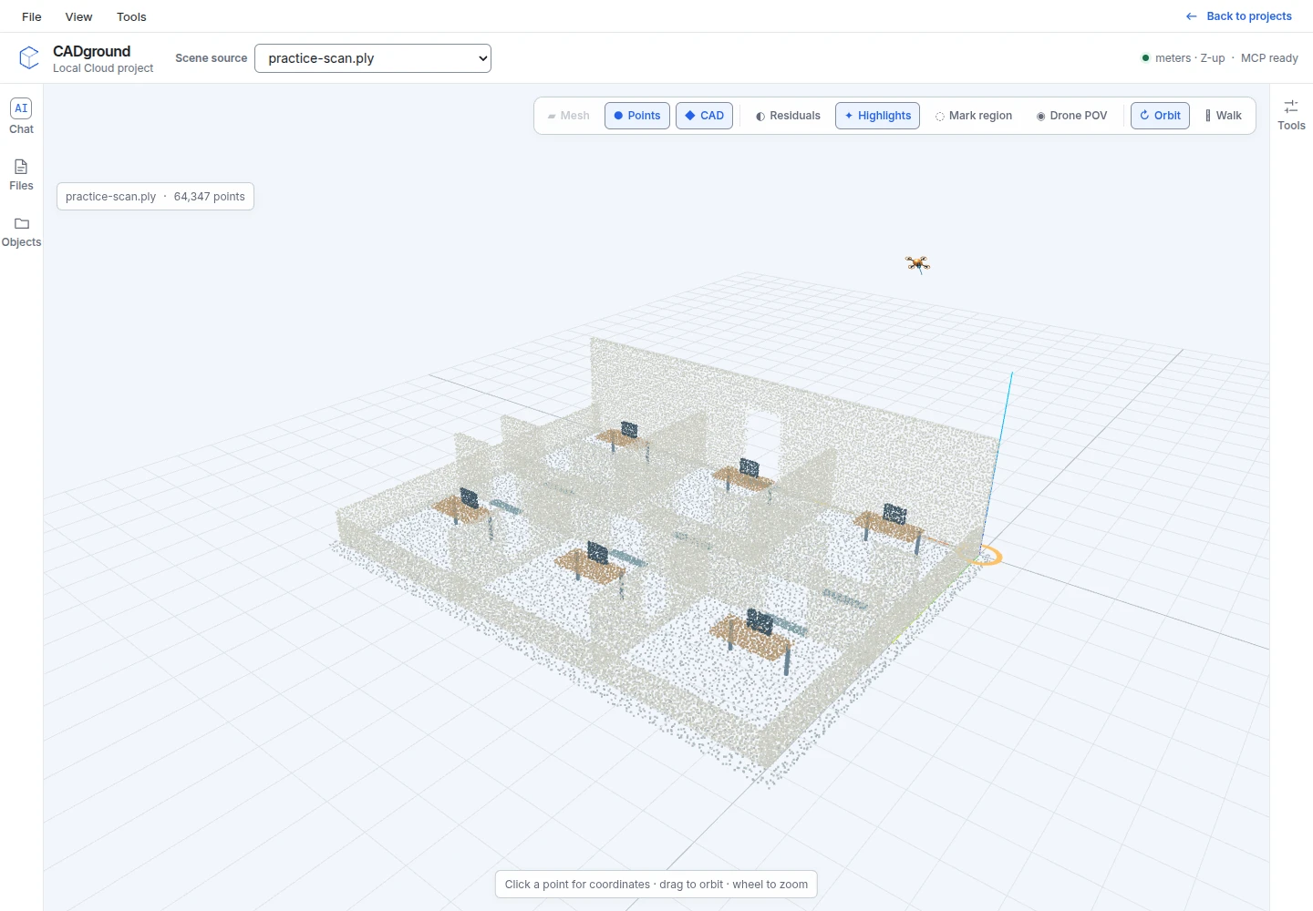
The practice scan has six rooms, a central corridor, door openings, and office furniture. The roof and upper internal walls are cut away. Two rear-partition patches are missing on purpose. Identify these gaps when reviewing the source.
- Scene
- Existing office · corridor scan-to-CAD example
- Practice task
- Check the scan, reconstruct corridor walls and openings, then compare the result with the source.
- File
- RGB point cloud · PLY · 64,347 points · 0.97 MB
- Coordinates
- Metres, Z-up. The scene has no geographic reference or stated survey accuracy.
- About the data
- Original synthetic practice data. Points were sampled from surfaces, then moved by small random amounts. The CSV lists the original dimensions used to create the scene. They are not CADground measurement results.
To try it: download the PLY. Create an account or sign in. Create a project and choose the downloaded file. Select Start with these files. Add the reference CSV through Files. Follow the steps below. The upload guide shows each control.
For the first exercise, model only the two corridor wall faces and their openings. Leave out furniture, ceiling systems, and rear partitions. The nominal clear corridor width is 1.44 m, between Y = 3.76 m and Y = 5.20 m. These are the dimensions used to create the source before adding random point offsets.
The sample is small enough to inspect fully. Its reference dimensions explain the exercise. They do not show the accuracy you can achieve on a real survey. Set the tolerance and output requirements from your job brief and source quality.
Define the scope, reconstruct, and check
-
Agree what to deliver
Record the area, elements, geometry type, coordinates, intended use, and checks required. “LOD 300” or “accurate model” alone is not enough. State which surfaces to model, how to show openings, and which differences from the scan are acceptable.
Agree the file format before starting. CADground exports STEP, STL, and CADground JSON. It does not create native RVT or IFC files. If the contract requires them, plan the remaining modeling and review steps in your BIM software.
-
Check the scan and references
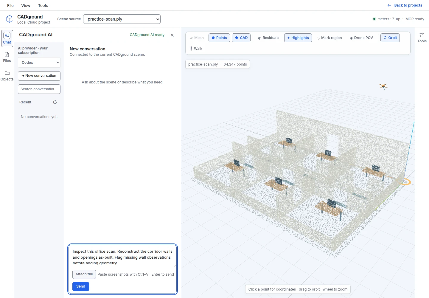
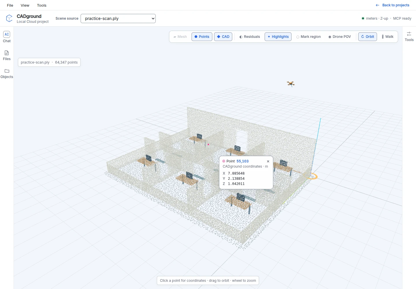
Open the scan. Check its units, direction, and a known dimension. Add the brief and drawings through Files. Inspect wall ends, junctions, openings, level changes, and areas behind furniture. These areas often need closer review.
Review this office scan before reconstructing the corridor wall faces and door openings. List the features the scan shows, missing areas, and questions that affect the task. Do not create geometry yet. Leave out furniture and rear rooms for this pass.
List each issue with a location that another reviewer can find. Missing data can change the time needed for the job. You may need to ask the capture team for more information before modeling.
-
Define the first reconstruction task
Start with one wall or one part of the corridor. Request as-built geometry unless the job needs idealized shapes. State how to handle openings. Ask the agent to mark boundaries visible in the scan separately from inferred connections.
Reconstruct the first corridor wall face and its visible door openings as-built. Keep the openings in the wall boundary. Preserve real differences from a straight or square shape where the scan shows them. Mark inferred edges and connections. Stop for review before building the second wall.
If the scan does not show both sides of a wall, supply a reliable thickness reference or leave the thickness unresolved. Do not report an assumed standard thickness as a measured value.
-
Compare the model with the scan
Keep Points and CAD visible together. Look from above, from the wall side, and through each opening. Check ends and corners from several views. Geometry can appear aligned from one direction and show a gap from another.
Run a fit check with the agreed tolerance where useful. Confirm which source region and CAD objects it checks. Furniture, excluded areas, or missing surfaces can affect a whole-scene score. Check individual elements as well.
-
Make a specific correction and check it again
Name the object and location. Describe the difference instead of asking only to “make it more accurate.” Ask the agent to correct that object and keep accepted work unchanged.
Check the second doorway in the corridor wall. Its upper edge looks too low against the scan points. Inspect it from both sides. Correct the opening if the scan confirms the error. Keep the other accepted openings unchanged. Show the corrected model over the scan.
Check the corrected area and its junctions again. Record unresolved geometry and explain why it remains unresolved. Creating an object does not mean it has passed review.
-
Test the exported file
Download the selected geometry and open it in the next application. Check scale, direction, position, and how the surfaces connect. Confirm that the next person can edit the details they need. A triangle mesh and an analytic CAD surface serve different purposes.
Include the agreed scope, source revision, comparison method, accepted differences, and open questions with the files. Upload the client’s report template as a project file and ask the agent to use its structure and style for the review report accompanying the 3D model. Plan any remaining BIM categories, families, attributes, and drawings in your BIM software. See files and exports.
State what the result must pass
The practice corridor is small enough for another person to check every requested feature. Use the same checklist for the first model and the corrected model.
| Check | Record | Acceptance question |
|---|---|---|
| Scope and source | Source file and revision, selected zone, included elements, exclusions. | Did we complete the agreed scope and clearly mark areas we did not check? |
| Representation | As-built or idealized; surfaces, thicknesses, openings and inferred connections. | Can the recipient tell which geometry comes from the scan and which uses an assumption? |
| Geometry review | Comparison views, tolerance, objects checked, and unresolved differences. | Are junctions and openings correct as well as the broad wall faces? |
| File delivery | Export format, units, coordinate notes, revision, and recipient’s import check. | Does the imported file contain the information the recipient needs? |
To estimate production effort, include preparation, agent work, review, corrections, and file delivery. Record who checked the result. A fast first model can still need substantial correction before delivery.
Practical questions
Is this a complete scan-to-BIM production system?
CADground provides tools for inspection, measurement, reconstruction, and review. It exports STEP, STL, and CADground JSON. Use your BIM tools for categories, families, project standards, and native RVT or IFC delivery.
What tolerance should we use?
Use the job specification, source quality, required geometry, and intended decision to choose a tolerance. State the value and check method. The practice sample does not justify a general claim of millimetre accuracy.
Can missing surfaces be completed?
The agent can propose geometry where the scan is incomplete. Mark each inferred part and review the reason for it. The practice scene’s rear-partition gaps are deliberately missing. Do not describe a surface added there as directly observed.
Can our own agent perform the reconstruction?
Use MCP to connect a supported AI client to the project’s tools. Check the workspace and scene before allowing geometry changes. Apply the same scope and review criteria as in the built-in chat.
Continue with reconstruction and reviewing the result. See also how engineers use a model of existing conditions.
Reconstruct one area. Check the result.
Learn the tools with the office sample. Then try one small real assignment and compare the time for preparation, reconstruction, corrections, and delivery.