
Engineering & existing conditions
Will the replacement equipment fit?
Ask your agent to check the space, access route, and service clearances in your scan. Compare proposed equipment with the existing conditions. Keep the measurements and source views with the design decision.
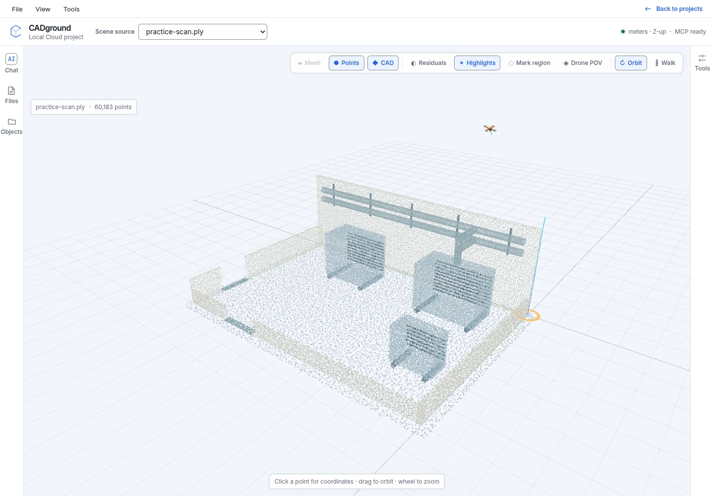
The question is usually more specific than “model this building.”
You may need one answer from an existing-condition survey to continue a refurbishment design. Does the replacement air-handling unit have enough service space? Does a pipe route cross a beam? Is the opening wide enough to bring equipment inside? Finding and checking those dimensions takes time.
CADground gives your AI agent a 3D workspace to investigate these questions. It can inspect the scanned area, measure source points, work with proposed geometry, and record the comparison. Keep the scan, proposed objects, source views, and corrections in one project.
“Where could we put the replacement AC unit?”
Supply the unit dimensions and the manufacturer’s service requirements. Ask the agent to check possible positions against the scanned room. Show the equipment body, installation space, service zone, and access route separately.
“How does the as-built condition differ from the plan?”
Add the planned model or drawing. State its units, reference levels, and direction. Align it with the scan before comparing them. Ask the agent to check the specific wall, opening, equipment item, or route that affects your decision.
“Can we recover the dimension we missed on site?”
If the scan shows both surfaces, ask the agent to measure between them and show the points used. If a face is hidden behind a cabinet or above a ceiling, mark it for a site check. Knowing which information is missing can help you plan that visit.
Try a plant-room replacement study
This practice scene has an open roof, two main equipment units, overhead pipes, a smaller unit, an electrical enclosure, and an access opening. The cutaway walls let you inspect the equipment layout and access route together.
- Scene
- Plant room · replacement equipment study
- Practice task
- Check the proposed equipment body, nearby obstacles, and scanned access opening.
- File
- RGB point cloud · PLY · 60,183 points · 0.90 MB
- Coordinates
- Metres, Z-up. The scene has no geographic reference or stated survey accuracy.
- About the data
- Original synthetic practice data. Points were sampled from surfaces, then moved by small random amounts. The CSV lists the original dimensions used to create the scene. They are not CADground measurement results.
To try it: download the PLY. Create an account or sign in. Create a project and choose the downloaded file. Select Start with these files. Add the reference CSV through Files. Follow the steps below. The upload guide shows each control.
For this exercise, use a proposed unit body of 1.80 × 1.00 × 1.90 m. Add the required service space separately. Choose a practice value and label it as an assumption. The sample’s nominal casing-to-casing gap is 2.20 m. This is the gap used to create the scene before adding random point offsets. That gap alone does not show whether the replacement can be installed or serviced.
For your own project, add the equipment datasheet and the relevant design revision. State the survey datum and any coordinate changes. Give installed and proposed objects different names so reviewers can tell them apart.
Check the design against the scan
-
Capture the room and the access route
Capture door openings, level changes, overhead obstacles, and the service sides of nearby equipment. Include the full route the replacement will follow. Add photographs of labels and connections. Check turning areas outside the main room as well.
Use a scan aligned by a survey professional when the job requires it. The capture guide also explains how to try a small scan yourself and check its dimensions.
-
Upload and confirm scale, orientation, and level
Create the project and open the scan. Add the datasheet and planned geometry through Files. Check a known dimension and reference level. When importing a model, set its source units and position. A model in millimetres will have the wrong scale if imported as metres.
The comparison guide explains preparing the source and proposal. Keep the original scan as the reference throughout the task.
-
State the decision and requirements
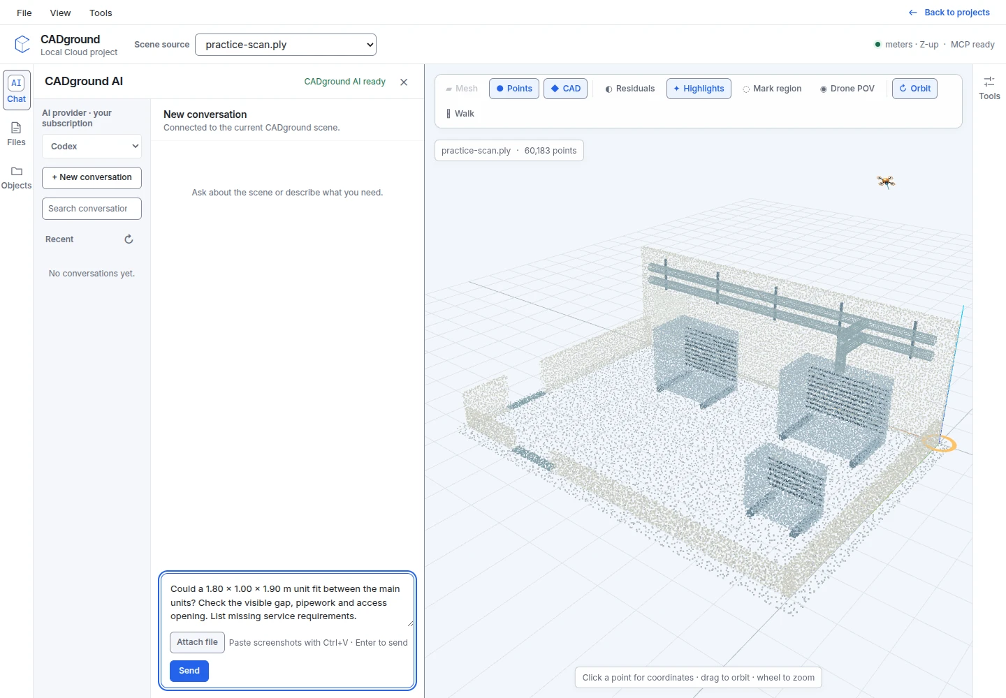
Tell the agent which position to check and what would make it unsuitable. Supply clearance requirements from the equipment datasheet. Ask it to list missing inputs before recommending a position.
Check whether a 1.80 × 1.00 × 1.90 m replacement unit could fit between the two main units. These are body dimensions only. Inspect visible pipes, the service side, and the access opening. List the clearance requirements you still need from the datasheet.
-
Measure the limiting features
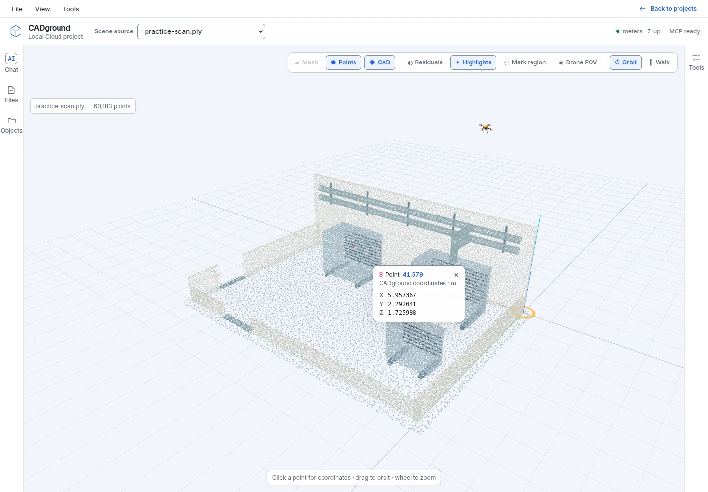
Ask for the gap between casing faces, clearance below the lowest obstruction, and the narrowest scanned part of the access route. Check endpoints or fitted faces in at least two views. Measure the horizontal clear width separately from a diagonal distance.
Measure the horizontal casing-to-casing gap. Check how it changes along the proposed footprint. Show the source points or faces used. Report the clearance below the pipe separately from its centre height. List areas hidden behind the existing equipment.
Check each measurement against the source points before using it to choose a position. A visible pipe diameter does not confirm the bore, insulation thickness, or connection type.
-
Compare the proposed equipment with the scan
Import an equipment model if you have one. Otherwise, ask the agent to create a simple shape from the supplied dimensions. Give it a clear name. Show the body and service zone separately. Place them in the agreed coordinate frame. Inspect them with both the scan and CAD visible.
For an as-built versus as-planned check, name the objects and set the tolerance. Ask for the differences that matter: object position, opening size, or surface shape. Check whether the agent has straightened or squared a surface that is uneven in the scan.
-
Record the decision and open questions
Ask for a short comparison report. Include checked dimensions, source views, proposed dimensions, assumed service requirements, and items needing a site check. Use the same requirements when comparing two positions. Upload your consultancy’s report template as a project file and ask the agent to follow its layout and branding when presenting the measurements and annotated 3D views.
Open generated files under Files → Outputs. Export reviewed geometry as STEP or STL if your next design tool supports it. After import, check the units, direction, and object positions.
Keep the fit study easy to check
The reviewer needs to know which limits came from the survey, which came from the design, and which are assumptions. Ask the agent to label these clearly.
| Question | Evidence to include | Review point |
|---|---|---|
| Does the body fit? | Named existing faces, measured clear space, proposed body dimensions and placement. | Check the full equipment body and parts that extend from it. A plan rectangle alone is not enough. |
| Can it be serviced? | Datasheet requirement, service-zone geometry and accessible working face. | State which clearances came from the datasheet and which dimensions were inferred from the scan. |
| Can it get there? | Openings, turning areas, overhead obstacles, and parts of the route missing from the scan. | Enough space at the final position does not prove that the unit can reach it. |
| What changed from plan? | Model revision, alignment method, objects compared, and tolerance. | Fix alignment or unit errors before reporting a difference from the design. |
Start with one dimension or one proposed equipment position on a job your team knows. Compare the result with your current method. Include the time needed to check, correct, and explain the result.
Practical questions
Does a geometric fit mean the installation is approved?
No. The scan helps you check visible space and obstacles. Installation also depends on loads, service connections, ventilation, access, and equipment requirements. Include these in the engineering review. The scan cannot confirm conditions it does not show.
Can it find concealed services?
A surface scan shows what was visible when it was captured. For hidden routes, use scans taken before walls were closed, photographs, drawings, or other suitable survey data. Ask the agent to name the source of each detail. It must not invent connections behind a wall.
Can I retain out-of-square existing geometry?
Yes. Ask for as-built geometry that follows the scan and set the tolerance. If you want straight or square design geometry instead, say so. Ask the agent to explain how it differs from the scan. See reconstruction and design intent.
Can I export a native Revit or IFC model?
Current CAD exports are STEP, STL, and CADground JSON. Native RVT and IFC export are not available. Test one exported object in your next application before planning a full BIM delivery.
Continue with the HVAC walkthrough, MCP setup guide, or reconstruction guide for survey teams.
Check one equipment location against the scan.
Start with the practice plant room. Then check one position using your own scan, equipment datasheet, and review requirements.