
Point cloud to CAD.Make the scan editable.
Reconstruct walls, openings and equipment from your point cloud with an AI agent. Check the new geometry over the scan, ask for corrections, and export a CAD file you can keep working with.
Start free · Already have an account? Sign in
“Reconstruct the corridor walls. Keep the openings. Show the result over the scan.”
Example request to your agent
- Source
- PLY, PCD or E57 point cloud
- Task
- Reconstruct and check geometry
- CAD output
- STEP, STL and scene JSON
You have the scan. You need geometry you can use.
A room, a corridor or the equipment in one plant area: give the agent the part you need to model. Keep the scan visible while you review wall positions, openings and object boundaries.
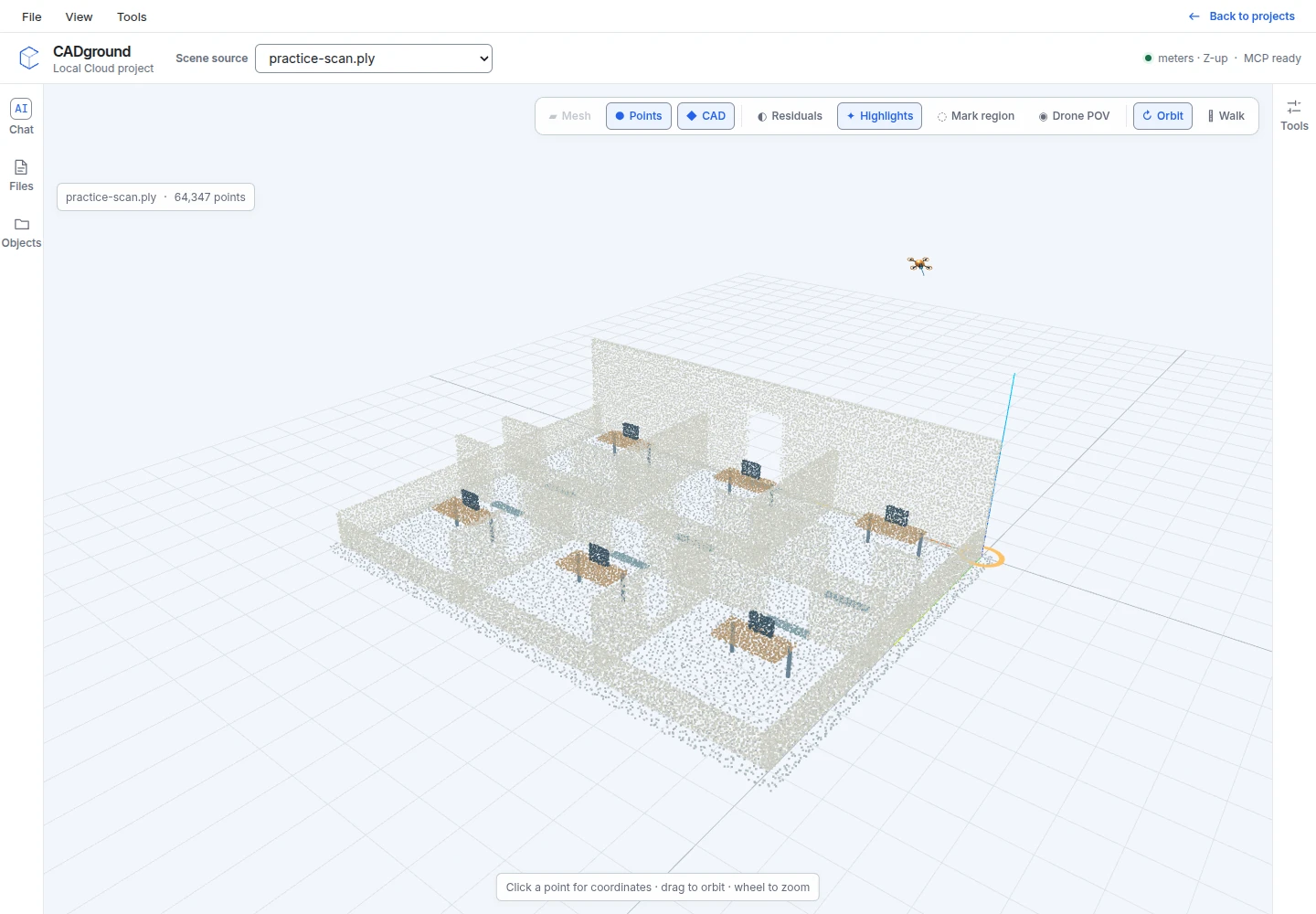
Try the office corridor
This office practice scan contains six rooms, a connecting corridor and door openings. Start with the two corridor wall faces. Leave furniture out of the model, and use the source points to check every opening.
- Keep the measured opening positions and widths.
- Check the 1.44 m nominal clear corridor width.
- Flag the missing rear-wall patches instead of filling them by assumption.
Original synthetic practice data, not a customer survey. Reference dimensions describe the constructed scene. Download the PLY, create an account, and choose it when creating a project. Upload instructions.
From your scan to a reviewed result
-
Upload the source
Create a project with your scan. Add a drawing, photo or known dimension through Files. Confirm the units and identify the area you want to reconstruct.
-
Describe the CAD you need
Name the objects, required detail and intended use. Ask for the existing as-built condition, or specify which features should be straightened for a design model.
-
Review over the points
Compare the geometry with the original scan. Check wall ends, openings and junctions from more than one view. Ask for corrections in the same chat.
-
Export the checked result
Export STEP for supported CAD geometry, STL for a mesh, or scene JSON to preserve the CADground scene. Open the file in your receiving application and check the scale.
Try this request in Chat
Reconstruct only the two corridor walls and their door openings in this office scan. Use the existing as-built positions, in metres. Exclude furniture. Show the geometry over the source points and identify any missing evidence. Check the clear corridor width before preparing a STEP export.
Adapt the objects, dimensions and output to your project. Read the reconstruction guide →
A usable handoff includes the checks.
Keep the model and the evidence together. Ask the agent to explain which objects it built, where the scan is incomplete, and what still needs review.
- Editable geometry
- Use STEP when the supported geometry needs to move into another CAD workflow. Keep meaningful object names so the next person can find the walls or equipment.
- Source comparison
- Review the same region with both the point cloud and CAD visible. Save useful views and record the dimensions you checked.
- Open items
- List missing surfaces, uncertain wall thicknesses and assumptions. Resolve these before treating the reconstruction as a finished deliverable.
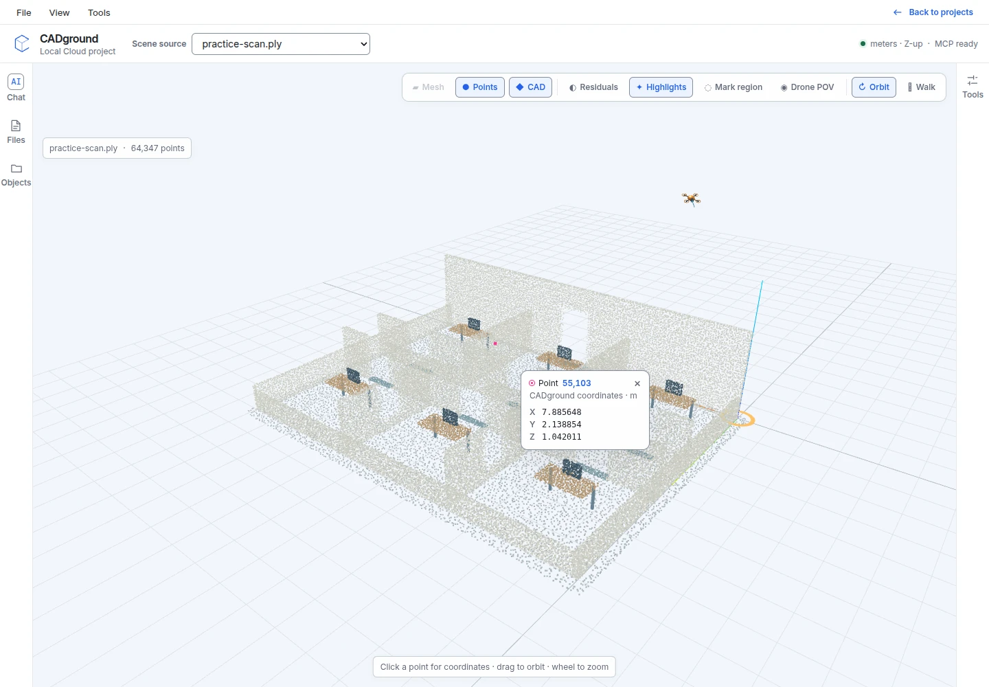
Before you start
Does CADground simply connect all the points?
No. A point cloud contains sampled positions. Ask the agent to reconstruct the objects or surfaces you need, then review the result. This lets you leave furniture, clutter or unrelated areas out of the CAD model.
Is this point-cloud vectorization?
It can be part of that workflow. Vectorizing a point cloud means deriving lines or other geometry from sampled points. For walls, openings and sections, describe the required objects and drawing or model output. For a 2D layout, see point cloud to floor plan.
Can I get DWG or DXF?
The built-in CAD exports are STEP, STL and CADground JSON. There is no native DWG or DXF export. If your handoff requires a drawing format, plan that drafting or conversion step in your CAD software and test a small example first.
What controls the accuracy?
The source coverage, point spacing, noise, scale and reconstruction method all matter. Check known dimensions and set a tolerance for the job. More displayed decimal places do not establish survey accuracy.
Can I start without my own scan?
Yes. Download the office PLY below, create an account, then choose the file when you create a project. The reference CSV describes the constructed example so you can check your work. The reconstruction guide explains the controls.
Turn one part of your scan into CAD.
Start with a room, a corridor or one equipment zone.