
Review and validate the result
Check the scan, model, and exported files before using them elsewhere or sharing them with a colleague.
Review the result in this order
- Confirm the source. Check project, scene, capture date, drawing revision, units, and the area analyzed.
- Read what the agent actually completed. Separate finished work from proposed steps, interrupted operations, and failed tools.
- Inspect the source and result together. Show Points or Mesh with CAD. Check opposite views. Then inspect the source and CAD separately.
- Check important dimensions. Review endpoints, fitted faces, direction, datum, and a known reference distance.
- Check missing scan data. Look for hidden areas, reflective surfaces, gaps, and geometry that the agent inferred.
- Inspect numerical fit results. Confirm the target, tolerance, coverage, and model revision they describe.
- Open the actual exported file. Verify units, object count, position, and important features in the receiving application.
Look from more than one direction
A model can match the front view but have the wrong depth, tilt, or back face. Inspect it from the front, back, left, right, top, and bottom where useful. These correspond to the positive and negative X, Y, and Z directions. For a room or site, also use angled views to check connections and clearances.
Look for doubled surfaces, floating parts, reversed faces, disconnected parts, and filled doorways. Check for geometry that extends beyond the scanned area. Hide and show layers to see errors that color or shading can conceal.
Understand fit evaluation
- Open the Tools window and locate Fit quality.
- Enter Engineering tolerance (m) based on the purpose and available source quality. For example, 0.01 m is 10 mm; that conversion does not mean 10 mm is suitable for your project.
- Select Evaluate fit.
- Ask the agent to explain the target geometry, source region, result, and areas with insufficient evidence. Show Residuals if useful.
- After a correction, evaluate again. Keep the result associated with the geometry revision that was checked.
A residual is the difference between source data and geometry in a particular comparison. A small average can hide a large error in one area. If too little of the object was scanned, the check may not support a conclusion. A fit check cannot improve the original scan’s accuracy.
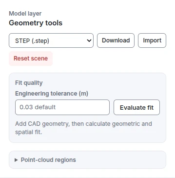
This screenshot shows the controls before a fit check. It does not show a passed result.
- Export format. Choose STEP, STL, or CADground JSON for the geometry or scene data you intend to save.
- Download. Export using the selected format. A raw point cloud does not become reconstructed CAD simply by choosing STEP.
- Engineering tolerance. Enter the tolerance in meters; for example, 0.03 m is 30 mm. Choose a value justified by your task and evidence.
- Evaluate fit. Run this after adding geometry. Read the result and inspect the visible differences. A fit score alone does not prove that the model is complete or the units are correct.
Keep evidence status clear
| Status | Meaning |
|---|---|
| Observed / measured | Based on source points or surfaces that you can identify, using a stated measurement method. |
| Fitted | Geometry estimated from a selected set of source points. Check its boundaries, assumptions, and differences from those points. |
| Inferred | A feature or connection that was not directly observed. Record why it was added and what remains uncertain. |
| Proposed | New design geometry, such as a candidate AC unit position. It is not part of the as-built scan. |
| Not validated | Work exists but has failed a check, lacks evidence, or has not yet been reviewed. |
Request a precise correction
Keep the checked floor and east wall unchanged. The west doorway has been filled in. Rebuild its boundary from the visible jamb and floor points. Leave the hidden top edge unresolved. Show source and CAD together, then repeat the fit check for that wall.
A correction to one part should not cause an unexplained rebuild of the whole model. Ask what changed and which checks were repeated. If the agent adds inferred geometry, decide whether it suits the task. Label it clearly.
Check files before sharing them
- The report names the source, date/revision, units, coordinate reference, and purpose.
- Measurements have visible endpoints or defined fitted surfaces.
- Drawings include a scale/reference, useful labels, and a legend where symbols are used.
- Unknowns and failed checks are easy to find.
- The exported geometry opens at the correct scale and contains the expected parts.
- Old draft files cannot be confused with the reviewed revision.
Geometry is only part of an evacuation-plan or equipment-placement decision. The floor-plan walkthrough and equipment-placement walkthrough explain which information you must supply from other sources.