
Fire safety & evacuation-plan providers
Build a measured base for your evacuation diagrams.
Give your agent the floor scan and current site information. Check the layout and visible openings. Prepare a measured base plan for your usual diagram tools and templates.
Get the building layout right before finishing the diagram.
An evacuation-plan provider usually delivers diagrams in an established template. Each needs the correct floor layout, direction, confirmed site details, readable symbols, and an editable source for later updates. A missing or outdated base plan adds work before you can prepare those diagrams.
CADground helps you inspect the scanned building and prepare a measured base plan. Give the agent a floor scan, available plans, and marked-up site notes. Ask it to identify rooms and openings, measure relevant dimensions, and list differences that need confirmation.
Start with a checked floor layout or a question about one revision. Keep the source views with the result. Review the diagram content and approve it through your established process.
“We have no current base plan for this floor.”
Use the scan to inspect the room layout and visible openings. Ask for a top view and measured outline. Check them before importing them into your plan software.
“A partition has moved. Which diagrams need updating?”
Compare the new scan with the supplied plan revision. Ask the agent to identify changed walls and openings. Use your diagram register to find which displayed sheets need updating.
“Can you prepare the layout for our template?”
Supply the page size, floor names, direction, drawing area, and accepted base-plan format. Ask for geometry or an image in that format. Check the symbols, text, routes, and revision details in the finished sheet.
Try a four-room office floor
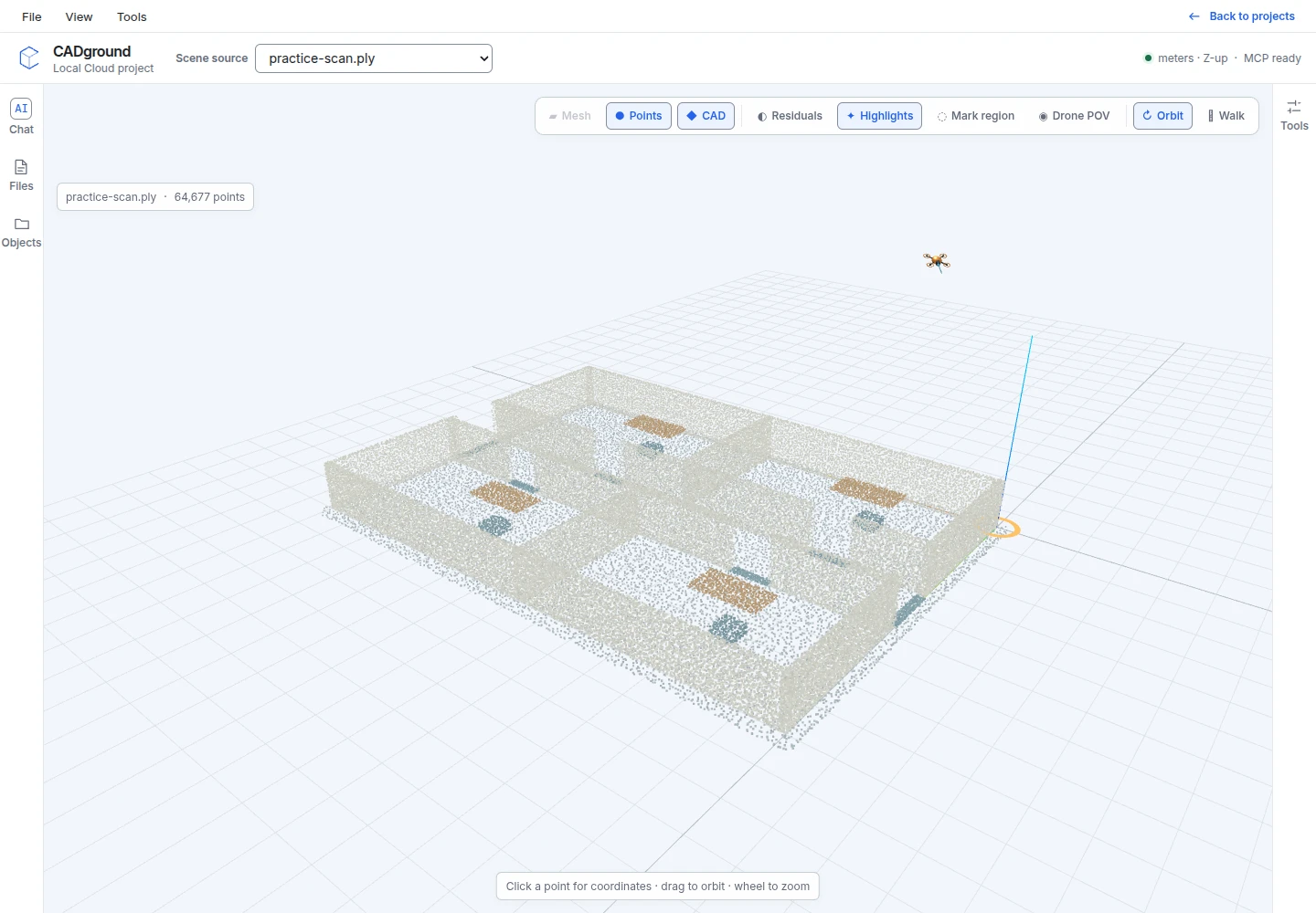
The practice scan has four rooms, a central corridor, four internal door openings, and two exterior openings. Walls are cut away at 1.30 m so you can see the layout. Use the exercise to prepare a measured base plan. List the site facts that still need a survey or records.
- Scene
- Office floor · evacuation base-plan practice
- Practice task
- Prepare a measured floor layout. List the site information still needed for the diagrams.
- File
- RGB point cloud · PLY · 64,677 points · 0.97 MB
- Coordinates
- Metres, Z-up. The scene has no geographic reference or stated survey accuracy.
- About the data
- Original synthetic practice data. Points were sampled from surfaces, then moved by small random amounts. The CSV lists the original dimensions used to create the scene. They are not CADground measurement results.
To try it: download the PLY. Create an account or sign in. Create a project and choose the downloaded file. Select Start with these files. Add the reference CSV through Files. Follow the steps below. The upload guide shows each control.
The nominal corridor width is 1.68 m and the exterior openings are 1.40 m wide. These are the dimensions used to create the practice scene before adding random point offsets. The scene gives no exit status, door operation, fire-resistance rating, assembly point, or approved escape route.
For a real job, add site notes and the diagram register. Identify the current drawing revision and label any proposed refurbishment plan separately. State which floor and display locations to review.
Prepare and check the base plan
-
Collect the existing plans and site observations
Start with the best available current plan. If it is missing or out of date, capture the relevant spaces and connections. Include corridor junctions, entrances, approaches to stairs, and floor-level changes.
Record facts the scan cannot confirm. These include room names, door operation, designated exits, equipment locations, and where diagrams will be displayed. Add dated photographs and marked-up notes.
-
Open one floor and confirm its orientation
Create a project and upload the scan. Add the current plan and notes through Files. Check the units, floor level, and a known dimension. Find an entrance you recognize before comparing the plan with the scan.
Ask for a top view of the selected floor with other levels hidden. Use the same room, opening, and junction names in the plan and review notes.
-
Ask for the measured base information
Start with the geometry. Inspect openings and connections between rooms. Do not ask the agent to guess which openings are exits or how they are used.
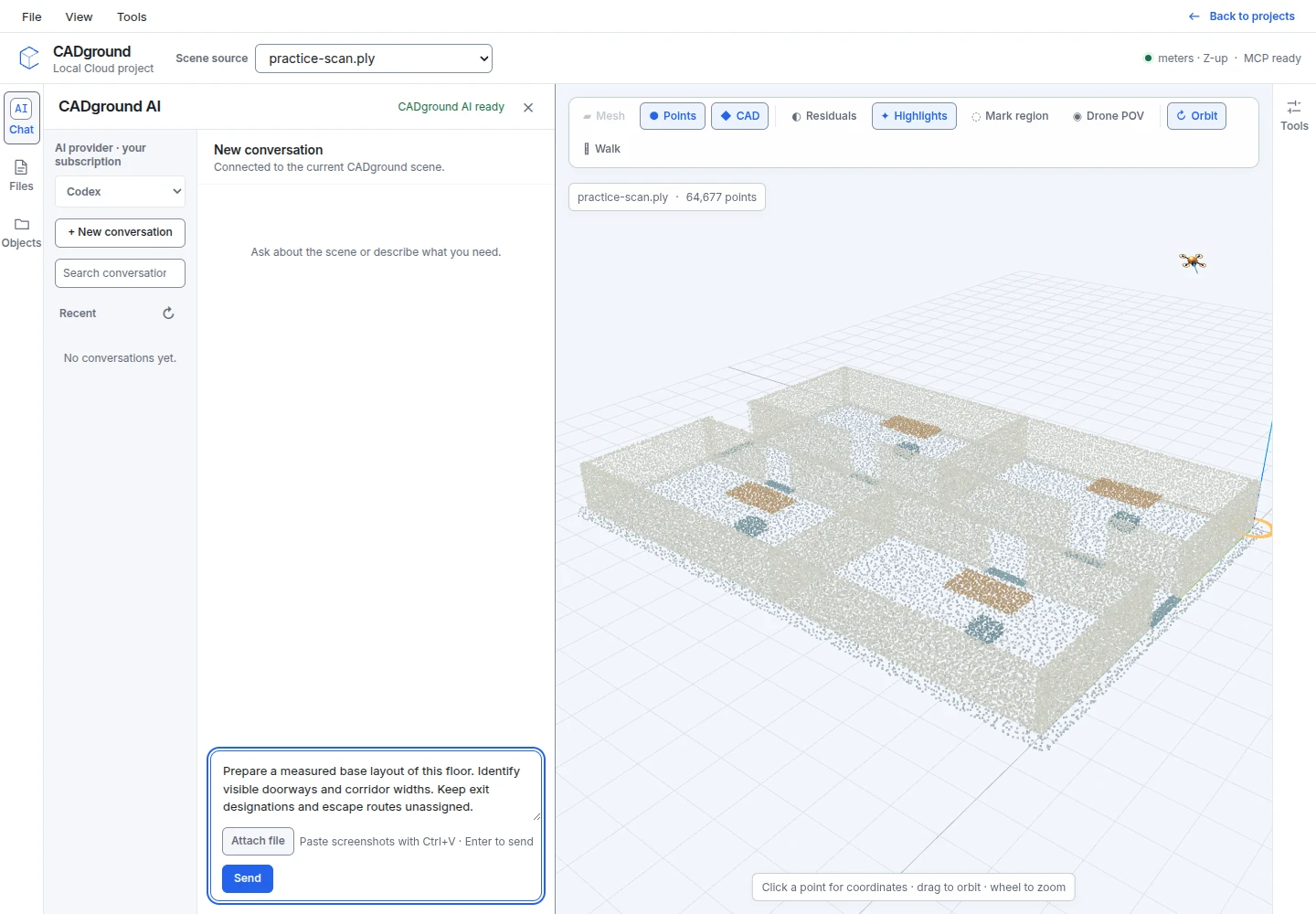
Prepare a base plan with room boundaries, the central corridor, and visible door openings. Use source points to measure corridor and opening widths. Give each opening a consistent ID. Do not assign exit labels, door swings, or escape routes until I supply confirmed site information.
When comparing an existing plan, ask for a list of changed walls and openings. Include views that locate each difference. Fix alignment or scale differences before reporting a change to the building.
-
Check each connection against the source
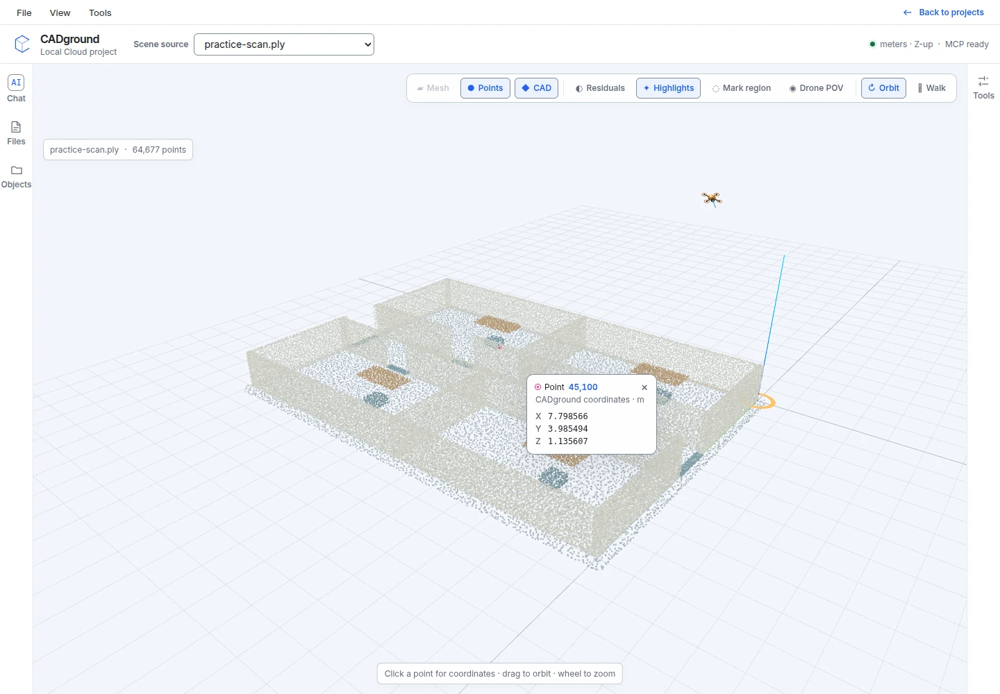
Inspect door jambs and nearby wall faces. Missing scan points can look like an opening. Furniture can also hide part of a real doorway. Check unclear areas from several angles. Leave the question open if the scan cannot answer it.
State which width you need. The clear gap between scanned faces differs from the nominal size of a door leaf. A scan also cannot confirm how a door operates. See the measurement guide to check the source points.
-
Add the confirmed site information
Supply the approved labels and site details. Ask the agent to record where each fact came from. Keep measured geometry, supplied facts, and unanswered questions separate in the notes.
Use my site notes to label openings and rooms. Keep the opening IDs in the review table. Flag each label that has no matching site note. Prepare the base plan for a person viewing it from the west corridor position. Do not invent an assembly point or approve a route.
Each display location may need a different plan direction and “You are here” position. Check these against the installation register and the actual view at that location before issuing sheets.
-
Finish and check the diagrams
Use the reviewed geometry, views, and notes in your usual template and diagram software. Ask the agent for a clearly named image or report if you need one for this step. Check generated files in Files → Outputs.
Inspect the printed sheet and open the editable source. Check the floor name, direction, symbols, legend, text size, and revision. Confirm that the content matches the display location. Keep unanswered site questions in the review record.
Separate the base layout from the site decisions
A moved partition is a geometry change. A changed designated exit comes from site information. Record both changes and their sources so you can update the correct part of the diagram.
| Information | Source | Review before issue |
|---|---|---|
| Floor geometry | Captured wall faces, openings, measured dimensions and comparison views. | Check the floor, scale, and connections. Mark missing scan areas. |
| Site labels | Provider’s verified notes and current records. | Check names and locations against confirmed site information. |
| Content for each display location | Installation register, display position, and viewing direction. | Check that each “You are here” marker and plan direction match the display location. |
| Finished package | Your template, editable source, print file and revision record. | Open the source, inspect the print and apply your established approval process. |
Start with one floor whose layout your team knows and a finished diagram you can compare. Record the work needed to create a checked, editable, printable result. Include the time to transfer the base plan into your template.
Practical questions
Do we need a point cloud for every evacuation-plan job?
No. A current plan checked on site may already provide what you need. Capture is useful when geometry is missing, inconsistent, or changed. Use CADground to inspect that scan and prepare the missing base-plan details.
Does CADground automatically produce an approved evacuation plan?
No. These steps help you prepare and check a measured layout. Your professional process still covers site decisions, applicable requirements, diagram content, and approval. The practice scene has no approved routes and does not establish compliance.
Can we keep our existing diagram template?
Upload your existing diagram template or an example PDF through Files. Ask the agent to follow its page layout, labels, and branding when preparing a draft from the reviewed 3D layout. Supply any additional requirements and check one base plan. CADground has no dedicated evacuation-template publishing system or native DWG/DXF export. It exports CAD as STEP, STL, and CADground JSON. Generated images and documents depend on the task and the agent’s available tools.
What about multiple floors and repeated updates?
Define each floor’s scope. Keep source dates, consistent opening IDs, diagram revisions, and the installation register. Start with one small update. Check the edited files before applying the process to the whole building.
Continue with the floor-plan walkthrough, review guide, or survey and reconstruction workflow.
Start with one floor and your own review process.
Try the practice layout. Then use your own scan, marked-up site notes, and template requirements to prepare one base plan.