
Find a place for an AC unit
Compare places for an AC unit on a terrace or roof. Check space around a nearby telecom antenna and the route to the unit.
The question to answer
To answer “Where could I install this AC unit?”, check four things: does it fit, can it be serviced, what blocks it, and how can it reach that location? CADground helps inspect and measure the geometry. Supply the equipment requirements. State which decisions need a qualified reviewer.
This example uses a terrace beside a room, with an existing telecom antenna. It does not set clearance requirements or approve an installation.
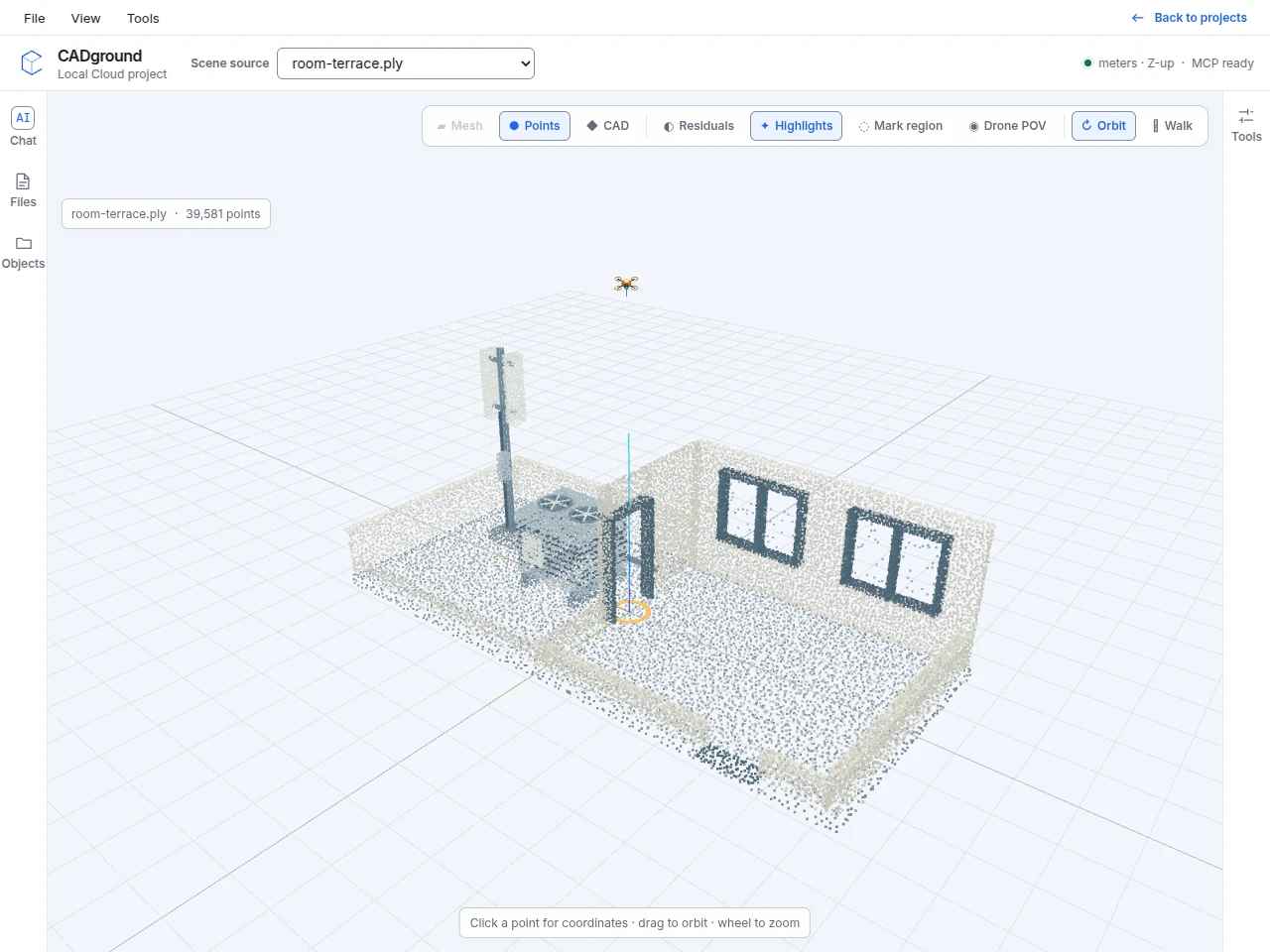
Captured in the local app with a synthetic scene. This overview labels the controls. The close-ups below show them at a larger size. CAD is hidden in this view so you can see the source points.
- Chat, Files, Objects. Use the left rail to ask the agent, browse files, and inspect available object or activity information.
- Scene source. Confirm the filename before giving instructions. Switching the source changes the scene you are inspecting.
- Display and navigation. Toggle Points and CAD, mark a region, or choose Orbit and Walk. A highlighted control is enabled.
- Tools. Open the right panel for the virtual camera, geometry exports, and fit evaluation.
Prepare the inputs
- A scan showing the terrace, room opening, parapet, antenna, and nearby equipment.
- The AC unit’s dimensions or a supported 3D model.
- Manufacturer requirements for intake, discharge, maintenance access, and installation orientation.
- Known site constraints: required routes, reserved areas, and the proposed access path.
- A known reference dimension and the scan’s units.
If the scan does not show the back of the antenna or the route through the room, record the missing areas. Do this before comparing positions. Do not assume these areas are clear.
1. Inspect the existing condition
Upload the files, open the terrace scene, and ask:
Inspect the terrace and the room beside it. Identify the antenna, parapet, doorway, and existing equipment. Show the available floor and roof area. Mark areas the scan does not show. Check the units against my reference dimension. Do not place new equipment yet.
Review the object identification and check that the entrance is an actual opening. A missing patch of scan data is not automatically a doorway.
2. Define the proposed unit
If you have a supported manufacturer model, select File → Import 3D Model…. Set its source units and check the displayed dimensions. If you only have a drawing, ask for a simple shape using the stated dimensions. Name it as proposed equipment.
Use the attached manufacturer dimensions to model the proposed AC unit. Name it “Proposed AC unit”. Show the equipment body separately from the space required for service and airflow. Cite the source of each requirement. List any missing requirements as unresolved.
A simple shape can represent the equipment’s outer limits for a space check. It does not show the equipment’s internal parts.
3. Compare possible positions
Compare two positions for the proposed AC unit beside the existing telecom antenna. At each position, check the required service and airflow space against the scan. Measure the smallest relevant gaps. Check the access route from the room. Show a plan view and angled views. Mark the objects that limit the available space.
- Check that both proposed positions use the correct surface and elevation.
- Inspect the antenna support and any parts that extend beyond the main body.
- Check space around the full equipment body and along the access route. A footprint check alone is not enough.
- Review each measured gap using visible endpoints or fitted surfaces.
- List any checks you cannot complete because scan data or requirements are missing.
4. Review a decision table
| Check | What the result should contain |
|---|---|
| Equipment fit | Proposed dimensions and direction, with the source of the dimensions. |
| Service / airflow space | Measured available space compared with the specific requirement supplied for the unit. |
| Antenna and other obstructions | The surfaces that limit the space, measured gaps, and labeled views. |
| Access route | Opening sizes, obstructions, and any parts of the route the scan does not show. |
| Unresolved design requirements | Requirements the scan cannot confirm, such as structural capacity, service connections, or equipment restrictions. |
| Recommendation | A comparison of the two positions. State what must be confirmed before installation. |
5. Prepare the files for review
Prepare a draft report comparing the two positions. Include the plan view, measured gaps, manufacturer references, and unresolved requirements. Keep the source scan unchanged. Save a PDF and labeled images. Export the reviewed proposed geometry separately if needed.
Download the files from Outputs and inspect the report pages. Send unresolved requirements to the relevant project reviewers. A space check does not confirm structural, electrical, radio-frequency (RF), acoustic, or regulatory suitability.