
Compare as-built with as-planned
Align the scan and design. Define the differences you need to check. Then prepare a comparison with views and measurements.
Gather the two sources
Use an as-built scan and a planned reference for the same area. The reference can be a supported 3D model or a drawing with dimensions and orientation. Tell the agent which file shows the existing site and which shows the design.
- The scan’s filename, capture date, units, and coordinate information.
- The planned model or drawing, its revision, units, and level or location.
- The features to compare: wall positions, opening sizes, equipment envelopes, or clearances.
- The comparison tolerance and its source, if the project specifies one.
A photo of a plan can help explain the layout, but perspective can distort it. Use a drawing with dimensions or an aligned model for a more reliable geometry comparison.
Add a planned model
- Open the as-built scene and keep its source visible.
- Select File → Import 3D Model… and choose a supported GLB, PLY, STL, OBJ, STEP, or STP file.
- In Import 3D model, give it a name that identifies it as planned, including the revision.
- Confirm the model’s units, Scale multiplier, source up-axis, and anchor. Do not use scale to disguise an alignment problem.
- Set the Anchor position in scene meters. Use viewport center can help with initial placement, but it does not register the model to the scan.
- Check the displayed dimensions, then select Import model. Inspect the result before asking for a comparison.
Attach a PDF or image in Chat. State the page and scale to use. The agent must align it with the scene; uploading the file does not do this.
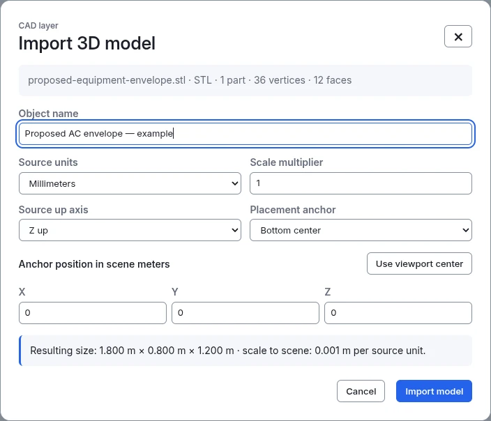
The box is an example of the space an equipment body occupies. Its dimensions were set for this example. They were not measured from the scan.
- Object name. Identify the imported part and whether it is a proposed design or an existing object.
- Source units. Select the units used in the source file. This example contains millimeter coordinates and uses a scale multiplier of 1.
- Source up axis. Choose the file’s up direction. Do not assume every CAD model uses Z up.
- Anchor position. Enter the position in scene meters. The selected anchor is the point on the imported model that will move to this position.
- Resulting size. Compare these dimensions with the equipment specification before selecting Import model. A factor-of-1,000 error usually means the source units need attention.
Align the sources before comparing them
- Check units independently for both inputs.
- Choose shared reference features, such as widely spaced corners or survey control points. Do not align only to the feature you want to check for a difference.
- Ask the agent to explain the proposed movement, rotation, and reference level.
- Inspect the alignment in plan and elevation, including areas away from the chosen references.
- Record how you aligned the sources and any remaining uncertainty. Keep the original coordinates. Record each change if you move or rotate a source.
The scan shows the existing room. “Planned room — revision B” is the design model. Check units, then align the sources using the agreed corners. Report the movement, rotation, and alignment uncertainty before comparing features. Do not move the scan just to make the disputed wall match.
Compare specific features
Once you accept the alignment, ask about specific features:
Compare the three named wall faces and two doorway openings. For each, report the planned value, observed value, difference, and units. Use a signed difference where it is meaningful. Show the supporting views or measurements. Use the tolerance I supplied. Label uncertain and unobserved features separately.
The agent uses CADground tools to do the checks you request. This is not automatic full-BIM clash detection or a certified compliance check. Comparing a PDF can need more interpretation than comparing aligned 3D models.
Review the comparison report
| Report field | What it should establish |
|---|---|
| Feature and location | You can identify the same wall, opening, or unit in both sources. |
| Planned / observed / difference | Values use the same units and a clearly defined measurement. |
| Alignment and datum | State the coordinate frame and reference level used for the comparison. |
| Tolerance and source | Identify whether the tolerance comes from the project, the manufacturer, or an example. |
| Evidence | Include labeled plan and elevation views, with references to the measurements. |
| Status | Use “within tolerance”, “outside tolerance”, “not observed”, or “unresolved”. Missing data cannot give a pass or fail. |
Check several results against the scene and reference file. If you change the alignment, calculate the affected differences again and update the report. Use Files and exports to download the checked files.