
Measure distances and clearances
Record what you measured, where you measured it, the units, and any uncertain details.
Before measuring
Check the source units against a known distance. Identify the surfaces you need and confirm that they are in the scan. The agent can sometimes estimate a hidden edge from a fitted surface. Label this as an estimate, not a direct measurement between observed points.
Use View → Fit scene or navigate to the relevant area. For a small object in a busy scan, mark a region or describe a clear focus. Measurements are requested in Chat or through MCP; there is no separate “automatically measure every opening” workflow to configure.
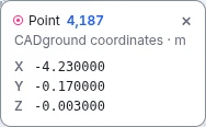
Click a scan point to open this panel. Point is the sample’s ID. X, Y, and Z are its scene coordinates in meters. This is one point, not a distance measurement. More decimal places do not mean a more accurate scan.
Open full-size screenshot (new tab)Define the measurement
| Question | Define it this way |
|---|---|
| Doorway width | Clear opening between the inside jamb faces, at a specified height. Distinguish the opening from the outside frame or trim. |
| Equipment gap | Clear distance between the nearest relevant equipment faces, including any protrusions that affect access. |
| Equipment height | Height from a stated base, slab, or ground reference to the top of the equipment. The largest Z coordinate alone is not the equipment height. |
| Floor or wall dimension | Name the two boundaries and whether the result is horizontal, vertical, in-plane, or a direct 3D distance. |
| Antenna orientation | Define the front face, the reference axis for azimuth, and how tilt or lean is measured. |
| Required clearance | Provide the applicable requirement and its source. A measured gap does not establish which clearance is required. |
Measure one feature
- Open the right scene and select Chat.
- Name the feature and request a view that identifies it before measurement.
- Ask for the measurement type, endpoints, units, and annotated result.
- Inspect the marked endpoints from another view. Points that overlap in a picture may be far apart in 3D.
- Ask the agent to repeat a doubtful selection or fit a suitable surface to clearly identified evidence.
- Check the result against a known dimension and record limitations.
Measure the smallest clear horizontal gap between the AC cabinet and the antenna support. Check the gap over the equipment’s full height. Show the points or faces that limit the gap. Report millimeters. Identify any surfaces that you inferred rather than observed.
Understand the distance being reported
A direct 3D distance is the straight line between two points. A horizontal distance ignores their height difference. A vertical distance is their height difference. A distance between fitted planes is a separate type of measurement. Ask which type the agent reports.
One pair of points may not show the smallest gap along an uneven surface. Ask the agent to check the full area that affects clearance. A doorway can also have different widths at different heights.
Work with noisy or incomplete scans
- Outliers: ask the agent to show whether the chosen point belongs to the surface or is an isolated return.
- Hidden edges: label a hidden endpoint as unknown or inferred. Do not report it as directly measured.
- Fitted surfaces: ask which source points and fitting method were used. Review the residuals—the differences between the points and fitted geometry.
- Scale: if all dimensions are consistently too large or too small, fix source units before measuring again.
- Precision: more decimal places do not mean greater accuracy. Report only the detail that the source quality and task support.
Record the measurement so it can be reviewed
Ask for a table with the feature name, measurement type, value, units, source scene, and any uncertain results. Include the endpoint or surface references. Add an overview and a close-up of the endpoints.
Create a record of the three checked gaps. Include the source filename and date. For each gap, give its definition, endpoints or fitted surfaces, and units. Add labeled views and any uncertain results. Save a PDF and a CSV in the project outputs.
Open Files → Outputs to find generated files. Before using them, follow Review and validate.